
Click for larger image
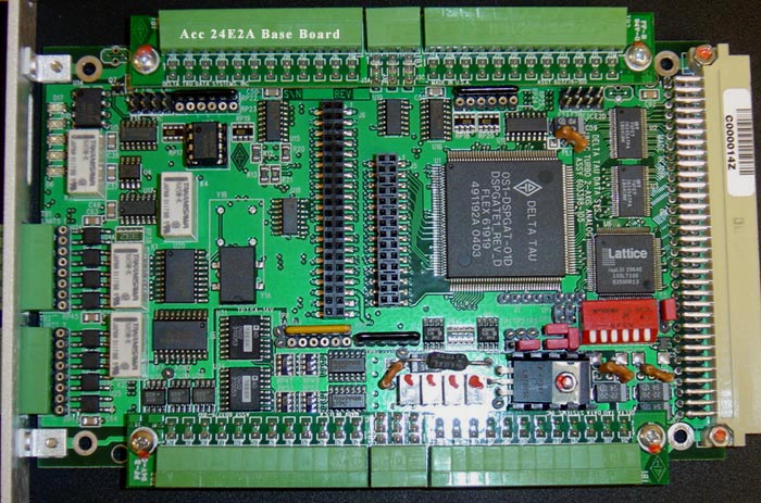
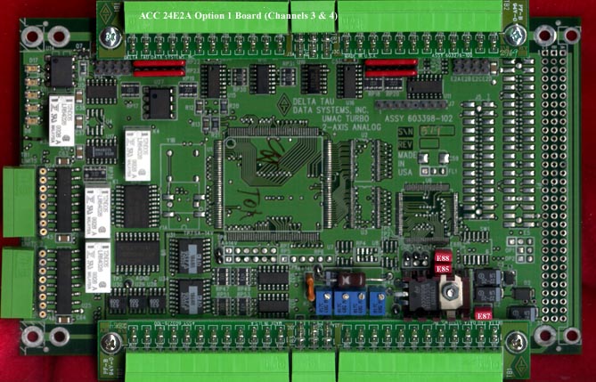
ACC-24 Axis Expansion Card for Turbo PMAC U3:
for the Option 1 board (piggy backed for axes 3 & 4, there is no change to the jumpers from the factory defaults.
for the Base board, the first card, must be configured to transmit phase and servo clocks. This is accomplished by setting Jumper E13 to 2-3 position. All other cards, must be configured to receive these phase and servo clocks (position 1-2). All other jumpers may remain at factory defaults.
For the SW1 address switch, configuration is as follows:
First Board: SW1-6 All On. This configures it for I Var range I7200 and address $78200.
Second Board: SW1 Off, 2-6 On. This configures it for I Var range I7300 and address $78300.
Third Board: SW3 Off, 1-2 & 4-6 On. This configures it for I Var I7400 and address $79200.
Fourth Board: SW1 and SW3 Off, & 2,4-6 On. This configures it for I Var I7500 and address $79300.
Fifth Board: SW4 Off, & 1,2,3,5,6 On. This configures it for I Var I7600 and address $7A200.
You must check I4900 to make sure that the Cards are at the addresses that you expect. If I 4900 is not what you expect it to be, then set Jumper E3 on the CPU card and reboot. This should reinitialize the CPU. Once I4900 is as you expect it to be, "save" the configuration and then remove the E3 jumper. For the scenario described above, I4900 should read $1C.
Troubleshooting ACC-24E2A Axis Cards
The Value of I4900 indicates the number of axis cards in the system in hexadecimal. The first two bits on a UMAC system are zero. Therefore, with one card in the system I4900 should read $4. 2 cards, $C. 3 cards, $1C. 4 cards $3C. 5 cards $7C.
For analog (±10V DC) output, I7mn6 should be 3. mn are determined as follows:
card 1: I7216=3 and I7226=3
card 2: I7316=3 and I7326=3
card 3: I7416=3 and I7426=3
card 4: I7516=3 and I7526=3
card 5: I7616=3 and I7626=3
There is a simple test for an analog axis card (ACC-24E2A). NOTE: ESTOP the machine before proceeding. Also,
to avoid any background PLCs overwriting your commands, set I5=0. Note: read I5 first so that you can reset it to its normal value
after testing is complete.
Enable and disable the axis to verify correct
operation by observing the amber LED labeled "ena" turns on and off correctly. To do this, address the axis through an "#x" command (where
x is the axis number). Then issue O50 ("O" as in open loop) to turn the amber LED on and put 5 volts out on pins 1 and 12. Issue K ("K" as in Kill)
to turn the amber LED off and zero volts on the analog output pins 1 and 12.
card 1: #1 and #2
card 2: #5 and #6
card 3: #9 and #10
card 4: #13 and #14
card 5: #17 and #18.
©1994-2023 TUS, Inc. 3434 Edwards Mill Rd. Suite 112-326 Raleigh, NC 27612 USA